Thursday, August 25, 2016

So the new Center Console project version 2 is going nicely. As usual Im under a bit of a time constraint, because Id like to have this project done and installed before the Labor Day weekend, when I plan to leave town for a few days!

Im getting the pictures arranged but Id like to start with the firmware. Its taken a bit to develop mostly because I never succumb to the old addage that " good is fine, better is worse". I started out simple wanting to chenge out the old LCD screens for new TFT LCD touchscreens. I wanted to reduce the switches on the console, and what better way to incorporate that than using touchscreens. They are a little tricky in that you need to make them trigger when you touch them, but how you touch them makes a big difference. For instance if you have big fingertips, sorta like I do, making the buttons on the screen really close together to maximize the space, wont work. You will end up with two buttons pressed instead of one, not good. But, if you narrow up the trigger area too much, you end up needing to use a toothpick to make stuff happen...its all about compromise.

The first arduino sketch Ill start with is the one for the GPS screen. In the old console I just had a LCD screen reading out lat, longitude, altitude and the satellites in view. In the new screen, I do all of that PLUS I added speed, direction, and a graphical representation of altitude including color coding the graph based on altitude...........

So the sketch..........

The first part of the sketch is like all the others. This GPS sketch is an adaptation of the GPS example written by the fine folks at Sparkfun for their GPS module. I had tried others but this one was the easiest and was easily adapted to what I wanted to do.

You will see all the libraries you need. Likewise I used the Adafruit fontconverter program using my Linux box and uploaded several new fonts. I like these fonts because they are easily read even at a 7,8 or 9pt font size.

You will also see I like to mess with colors. Most of these arent used but I usually import all the RGR565 colors I have used in the past to see how things look
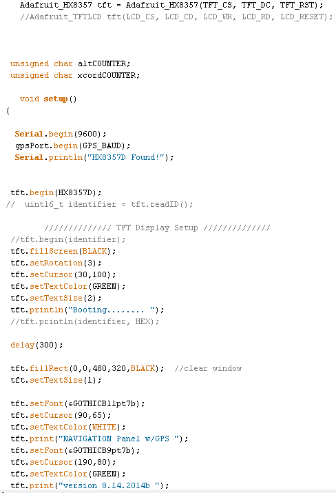


  This next section is nothing more than setting up the TFT screen, clearing the screen when starting or rebooting, and then a little splash screen just for fun


           This next section does nothing more than set up the individual windows in which the real time(ish) data will be displayed. I say real time(ish) because when displaying stuff on a TFT screen you must destroy the previous data displayed and rewrite the new data. With everything Im displaying, this all takes about a second using the Arduino Mega....so all updates are roughly every second. There is alos a built in delay in the sketch to allow new NEMA sentences to be fully read and displayed


Finally the rest of the setup showing where I set the MPH units for the speed window, the Altitude graph box area and two counters, which Ill explain later.


The simple void loop. It calls the main GPS data printing loop and also adds the 1sec delay to ingest all the NEMA data


This is where the fun begins. The GPSInfo loop. At the begining of the loop you will see that counter that I initially set to 0 in the setup up. This counter will increment by 1 with each pass of the loop. The rest of this section is showing the typical

set up for displaying the data. You remember in the SETUP we created the data display window. We ingest the data, then before displaying it, we destroy the old data with the tft.fillRect( ) statement. This paints a black square over the old data the same size as the box we set up in the setup. This way we retain the original set params and clear the window. The rest of the commands are setting the font, font color, location and finally printing the new data. This is done exactly the same for all the windows.

Altitude graphing:

This is the Altitude graphing section. I actually have two altitude sections. One is a simple window that dispays the current altitude. This section take it a step further and shows a histrogram of the altitude over about a 35 min period in which we have traveled.

The altCOUNTER is the counter we increment by 1 with each pass. Therefore with the counter reaches 16 ( it starts out at 1, with the first pass) this sets us up for making a altitude graph entry ever 15 secs.

Then I do a little math. All of the variables are floats. I know it takes a little  arduino horsepower to do floats, and yes I could have declared them earlier, but I did this over a couple of days, and in sections so it

ended up like this. All you programming gurus out there please dont slam me with a bunch of comments, I acknowledge its not pretty, but functional. yyfeet is the actual reading from the GPS in feet like 456.78ft of altitude. next to reduce this so I can fit it on the screen of the TFT, I divide this by 100. The reason for this is my graph will show a traversed path from 0 to 10000ft of elevation. I would suspect I probably wont drive to Pikes Peak, or anywhere above 10000ft, if I do the graph will just brickwall at this elevation. So now we have a altitude of 456.78ft, reduced to 4.4567.

The window to display the graph is a window thats 100pixels tall ( 10000ft) and 400 pixels wide. Originally I had the graph display a 10 minute traveled path, the final result is much longer. if you take the 400pixels and divide it by the 15 sec measurements, you get a little over 9 mins which was my original thoughy.

The coordinates of the window are 30,319. just a little left and nearly at the bottom of the tft screen which is 320pixels in height The ycord = 319-yy is to make the y coordinate land at the bottom

The xcord, is the x coordinate. Since we want to display the altitude over a time frame, its necessary to plot the x coordinate, and one the next measurement move this to the right by some fixed distance and plot the new data. This way you end up with a series of rectangles, drawn based on the altitude (yy). Since we are using the tft drawRect( ) command, you need an x coordinate, a y coordinate, a height, a width, and a color) so then we just substitute in all our variables and we tell the arduino to draw a rectangle based on the altitude.... or.....

   tft.fillRect( xcord,ycord,2.5,yy,BLACK)   this tells the arduino to draw a rectangle at the current (x,y) coordiantes, with a width of 2.5pixels, at a height of (yy) which is our calculated height in the color BLACK.

Now in order to get the arduino to draw the new altitude rectangle to the right of the last one so we have a history being drawn on the screen..... we have to add in another counter. This counter (xcordCOUNTER) counts the rectangles drawn and when it gets to 144, then it will wipe the graph clean and start over with a new one. xcordCOUNTER reaching 144 is enough to show a traveled history of 36 mins ( 144counts * 15secs = 2160 / 60 = 36mins) You can change this to whatever you want.

All if the "if" statements preceding are to change the color of the graph based on the altitude. From 0-5280ft the graph is black, from 5280ft to 6000 ft its CYAN, and so on......


Direction Traveling:

The only other thing I did was change the way that the arduino take NEMA data and displays your direction traveled. Originally I just printed out the heading in degrees, but of course I had to change it. I like the result...it adds several lines of code but it works. Basically I take the GPS Course data, and tell the arduino to look at it and based on the IF statements display whether we are going North, South, Ease or West. I then decided if I did that might as well add in the NE, NW, SE and SW directions too. The arduino looks at the course reading, and picks the direction corresponding to that heading. I simply broke the entire 360 compass into 45 degree sections.


Finally here is what the screen looks like. The graph at the bottom unfortunately is nearly flat because its sitting in my room....but it works


In the meantime.........happy coding!


Wednesday, August 24, 2016

Center Console Version 2!

So its been a while since I posted, but that doesnt mean that I havent been working on things. Since the last I posted, I have added a APRS digipeater, and Igateway, to funnel APRS from the RF world to the Internet. I have also built an additional echolink /allstar node for the local radio club which Ill outline in another post. Also I have put up more antennas, and changed my workspace some. All of this was prep work for my new center console project for the car.

As you may have read I did an earlier version of this back in 2014, which turned out nice. It worked great but to one flaw. It was small, and it wasnt as sturdy as I thought. My kids, getting in and out of the car, accidentally kicked the old console and eventually it developed cracks, and started to show signs of falling apart. I wasnt that mad, because I have always decided I would build a new and improved version of this concept. I proud to announce, that all the firmware is written, the testing is done, and I am ready to put the pieces in place. In the next few days or so. Ill document the construction, wiring and results of several weeks of planning, and designing the new console.

Stay tuned............
In the meantime as always...........happy coding!


Monday, March 28, 2016

Prototype online, new discoveries


So the finishing touches and the tweaks begin on the Naked Node. I went ahead this weekend and finished up the last little construction and configured the BeagleBone computer, as well as the echolink configuration as well.

The node works, proving that that circuits work. I was able to drive more than 3 miles away and get into the node from the car. I have discovered though that there is still an RF problem. When the radio keys, after receiving a signal, and then you try and talk into the node from a handheld, it seems that the micro-controller has a bit of a lag recovering from one mode to the other. Not sure if this is because of the code, RF getting into it, or a design problem. Sometime I have to key the radio a couple of time before the node responds. I noticed that the heartbeat LED on the micro-controller, stops for a second or two and then restarts back blinking. This is telling me the firmware is stopped running and then restarts. Im looking into both the code, and perhaps toning down the radios power output even more.

In the video, two fellow hams are talking. You'll notice that I slapped on the 20x4 LCD. I did this so I could go ahead and run some tests, before adding the touchscreen. Its all part of the design process, working out what bugs you might not have anticipated. The tow hams are located in Arizona, and Long Beach, CA. I didn't catch the calls.


So work continues, as I finish up this node, and make preps for a improved node in the future, as well as lessons learned for the continued repeater build coming later this summer.

In the meantime.........

Happy Coding ( and building)


Wednesday, March 16, 2016

Final touches on the Display

So works continues on the Naked Node Project. I have been concentrating on the display. I wanted to add some additional features, and have a couple more to add, but Im enjoying the challenge.

I added two additional buttons at the bottom of the screen to turn the radio and the computer off and on via the touchscreen. I have to admit calibrating the touchscreen is a bit of a chore, especially since this screen isnt the greatest in the world. I ended up chopping up the parts of the sketch for the screen into multiple voids, so that the main loop would run faster. The original way I had it caused you to push the buttons multiple times before the request registered on the MCU. Chopping up everything made this a lot faster. There are a few occasions that I have to push the button twice, but that ok for this project.

As promised I will show the S- Meter animation. Its not the greatest video but you get the idea


S Meter Animation


I also as mentioned added two additional buttons. Each button is now capable of turn the radio or the computer off and on using a single key. When the equipment is ON, the button changes to a filled color, when its off, then its just a void button. I had a lot of fun getting one button to do both desired functions, but it works.


                            When the equipment is off, this is how the voided out button looks


Buttons have turned on the equipment

Though the photos dont really do justice, the radio button is actually green, and the computer button is a light shade of purple. The lighting messes with the hue of the photo.

This is about it for this update. Work continues on the project. Ill post the code once its all cleaned up for those that might wanna see whats going on.

In the meantime..........

Happy Coding!


Tuesday, March 15, 2016

Little Suprise....the Cherry on top

So work on the node continues. I decided to kinda take the node to the next level. I realize that its a bit over the top but I like my projects that way.

I finished level 3, the radio level, and decided to add a 4th level. Most will say that its unnecessary, but in reality I wanted to do this because its the precursor to the front panel of the repeater. So what is it?  Well I added a display. The first version was an I2C 20x4 LCD. I had one laying around so I decided to use it. Being that its I2C it was easy to interface, and a snap to write the code.......

Then of course I changed my mind. In reality I changed it for a good reason. I had an older 3.2 inch TFT screen available. I decided that I would try that. It wasnt bad to interface, and though a little more difficult to program I think the result looks clean and nice. Im not a huge fan of a lot of clutter, so I kind of modeled after the ICOM IC-5100 their first generation D-Star radio. I finally added a splash of color as you will see and I animated the S Meter as well. Here are the shots, one with the radio in transmit and the other receiving a signal

My inspiration was the IC-5100 by Icom.


Im a big fan of graphics. I just think the IC-5100 display is clean, easy to read, easy on the eyes and really looks professional. It was what I used to model my display after.....Thanks ICOM!


I havent added everything I want to the screen. It is a touchscreen and Im working on the bottom row of buttons, which will eventually power the system off and on, and maybe kill the radio while leaving the computer attached to the network. I liked the font I found which gives the screen a clean look and not just ordinary. A font conversion utility from an engineer at Adafruit turned me on to converting and uploading my own custom fonts, which I have to say once you learn how, it makes ordinary TFT screens really stand out.

When I am fully finished Ill add a video of the screen in animation so you can see the S Meter in action. Once Im done editing as well Ill post the code for the screen.

In the meantime, work continues on the Naked Node. My hope is to have the Node finished in the next few days, depending on available free time..........

In the meantime

Happy Coding!


Monday, March 7, 2016

Naked Node work continues with Part 3

With the Control layer done and wired up, its time to start on the next layer. This next later is one of the easier ones, the computer layer.


The Computer layer is pretty basic. Its consists of a BeagleBoneBlack credit card computer running a version of Allstar link, the image written by WA3DSP. You can also see the soundcard FOB that will be modified and fed to the control layer.

The SMAKN module is  the battery eliminator for the node radio. Commercial bought, this module takes 12VDC and converts it to the 3.7VDC needed by the radio. Its just simpler to buy this commerical converter than it is to make one, wait on the boards, and populate them. Its cost a whopping 5 bucks off amazon.com.

The only other thing to show here is the underside of this layer


The underside I have added to save space, a relay module. Again this was also bought commercial for another project that I decided not to do, so I used it here. The MCU will connect to this module and command it to do what I want. Its just easier to used this than try and make one myself. In this case both the battery eliminator and the relay module saved alot of time. We can see I started wiring up the battery eliminator to the relay. One will turn on and off the radio, the other relay will turn on and off both layers 1 and 2. This way I can kill the radio, yet say connected to the Allstar network if I wish, and then turn on the radio when I want the link active.

Thats really it for Layer 2. Nothing really complicated here. In the next post we will move on to the radio layer, layer 3, and the final layer which is a surprise for now

In the meantime as always

Happy Coding!

Naked Node Part 2

So the work on the Naked Node continues. Seems I have found myself with some build time, so I decided to take full advantage. The Node is built in layers, each layer, for me, is a different function. Some may look at it and say this can be built a lot less complicated, and a lot smaller, but for me thats not the point. My point in all of this is to make a fully function node, broken into modules, that if something were to go wrong, troubleshooting can be simplified down to a module, and the module or even a layer, could be switched out, and Im back in business. Likewise, if I want to play and add features, I can use the basic building blocks to do so, even reconstructing a layer on the bench, adding what I want and then swapping in the new layer for the old....

So the bottom layer is the brains. As I discussed before, the larger board is actually on old repeater control board, all be it a flawed design, I could re-purpose it for this project by modifying the board. In your design, and when I get around to it, I have already designed a replacement for this board thats a lot smaller, and does the job. In my case, with the bad boards I had, I could go ahead and start on this and visit it later to replace the re-purposed board. You could even design something to do the same job. The cool thing with this is you can be the designer. The basic building blocks of this are simple to use, easily available, and not hard to modify, so have at it.......

Ill point out too that each layers base is built on 3/8 thick plexi-glass. I both love this medium and hate it. I love it in that its readily available, and with just a Dremel tool, I can cut and shape it, with not too much mess. The finished product looks clean, and cool. Its light weight as well. The cons are of course you cant solder to it, grounding things takes a little thought process since you cant use the layer as a ground, and drilling.........oh the drilling. I have broken several nearly completed layers using a brand new drill bit and a variable speed drill. I finally found out if you put painters tape on the area to be drilled, especially if its close to the edge, mark the holes and carefully at slow speed drill until your are almost through, reverse the drill and carefully push the bit the rest of the way through, actually melting the remaining material out of the way, you end up with perfect holes. I broke 5 of these layers before I found the combination that worked....I think perhaps in later designs I might switch to aluminium stock....this is a prototype after all

The bottom layer consists of the modified controller board, a MCU, a repeater module, a buffer board and a FOB interface board, all of which were originally designed for the repeater. Since I had extras, I just populated the boards, and left off what I didnt need.


Figure 1


Figure 2

The boards are visible here. You can see that the controller board is huge, in my case 4inchs x 4inches. This is total over kill, but remember, these are useless for the repeater, so why not use them here. You can see as well that there is a lot of unused ports. The port next to the Arduino ProMini328 interface board, is what would normally be the MCU display board running a touchscreen on the controller unit in the repeater. Likewise, there are two smaller header ports, one for a Control radio link transceiver, and one for a remote base. Of course both arent used here.


The MCU interface board is nothing more than allowing me to take a smaller Arduino ProMini, and turn it vertically making use of the vertical space instead of having to make a bigger board. Its also removable, and able to be programmed in place with a laptop if I want to upgrade the firmware. I have also broken out the SDA and SCL pins so that in the repeater, a I2C LCD screen could be attached for troubleshooting problems. Ill explain more of that when I write up the repeater build, for now its just there. The arduino works just like any other arduino, I just mounted it vertically is all so I can squeeze 2 of these MCUs on one smaller 4x4inch board.......saves on PCB costs.

The USBFOB board is located in the lower right hand corner of Figure 2. You can see the baby blue BAT43 diodes that stand out.


The USBFOB board is a simple design. Many that have ALLStarLink repeaters, nodes and other equipment have used the StarTech USB sound card to interface a computer with the Allstar network. These works great allowing for radio carrier detection, PTT, and audio interfacing. I designed a little board to allow nearly all of my connections to the USB soundcard, to be made external so that I could minimize the amount of soldering to the CM108 chip in the FOB. I can do SMD soldering, but this way I  simply remove a LED, and make just 2 solder connections to the CM108 chip and Im done. I dont have to solder transistors, diodes and all that in the FOB. Conversion of the USB Sound card can be found on the web, Ill cover my mods later, for now here is the schematic of the board I made, and this is plugged directly into the repeater control board....or better in this case my node controller card. Note to I add notes to my schematics, its just for me, that way if I have to fix something, I dont have the ask myself...ummm " why is that transistor there again"..........just saves time.


Finally beside the radio module ( which I have covered in a previous blog) this is the buffer board. Now this board isnt totally necessary. I like to use a buffer when I am sending signals from one unit to the MCU. This cant be done several ways, some use ICs, some use pullups and pull downs, I like to channelize things. Its a little more work, but it gives me a clean 4.3V HIGH signal and a clean LOW signal to take in from a module, and send it to a MCU. I also like to plcae a diode on the output path. You can see several of these in Figure 1. This provides isolation as well between the buffer and the MCU. I like to keep the MCUs isolated, and with transistor output, everything is clean and loading between stages kept to nearly zero. Its an old habit from decades past. I relaize you can put IC buffers in there like a 74HC07, or similiar, but when you have 300 2N3904s and 3906s hanging around, you tend to use them when you can....The buffer board is noninverting, two stage board, what goes in is what comes you at a pure 5Vdc, the .7Vdc drop is the isolation diodes I mentioned earlier.


The last thing to mention is I did go with a commercial LDO voltage regulator, seen on the left in Figure 2), they are fully adjustable from 1.5 to 37Vdc. I love the LM2596 chip! Its also handy to have the 7 segment readouts, no meter needed. You simply feed these with 12Vdc, adjust down to 5V, done!

I havent covered programming ht MCU, Ill write more in a later blog about the firmeware. For now this covers the bottom layer! More later

Happy Coding!

Tuesday, March 1, 2016

Little fun with VOIP/ Naked Node

So its been a while since I posted anything, and thats mainly due to the fact that the end of the year, especially fall and winter is chalked full of things to do, not to mention the holidays! Never fear though Im always dabbling in something.......

The project I have been working on actually formed out of a couple of mistakes. I got the boards in for the repeater controller and after about 2 hours of putting parts on them I discovered a couple of mistakes. One of these mistakes, routed an output signal to the wrong input, and another found a trace that hadnt been put on the board. Both were my mistakes. I learned the hard way now that if you dont run the board through an ERC error check, or like I did, went through it really fast, you end up with a board that could cause you lots of fits.....I discovered this the hard way, fits and all.......so what to do. I made the mistake, all be it, a 20 dollar mistake. So I thought about it for a while and relaized that while I couldnt use the board in the controller, I could re-purpose it for something else ( and yes I resubmitted the correct boards to the fab house.......again......

I was cruising around on the web, and found something that looked like I could have fun with. Several hams have used the concept of a private ALLSTARLINK node and taken it a step further, creating what many called the " Naked Node" The Node is nothing more than a radio link to the Allstar Network, using a simplex radio on UHF or VHF. You house the node in an open non-boxed concept leaving the internal boards and all naked to the visible eye. Many hams have done something like this including W0ANM, WA3DSP and KP4TR, you can check out their web pages via google, or search Naked Node.......

I had the extra Beagle bone black v4, the botched control boards, extra UHF handie, and a few things I needed to order. I thought, heck why not. Of course the Rich curse slowly kicked in. This went from a simple node to something I have added to and added to but hey, building is what I do, and enjoy, so if I choose to make it a bigger thing than needed, its just the way I like to have fun.

The radio was pretty easy to modify. I had a BF-888s, in fact I have 2. They are cheap, easy to part out and modify. There were some web sites that had excellent step by step instructions on how to do this.


The bottom picture shows the radio after first opening it, and the top shows the radio after the modifications. Aside from needing to pull the entire circuit board out, and some desoldering, the whole mod only took about an hour. When I was done, I could remotely key the radio and had a positive going COS ( carrier present signal) as well as both mic, and received audio. For now Im concentrating on the control circuits, so I havent fiddled with the audio just yet.

Once this was done, I turned my attention to the control board, or rather the botched repeater control board. I looked and though its a rather large board, and a lot of it will be unpopulated, I went ahead and used it, making the modifications for simplex use. Since I had designed it, fixing what I needed wasnt that bad


It doesnt look like a lot of modifying, because in reality its not. In order to make the board work, I had to add a couple of jumpers ( which I admit I hate) and removed a feed through from one module to the other. Breaking this line I had to tack solder a jumper in to reroute the signal. I went ahead to and added a Dignal line ( D9) coming from the Arduino, and ran this out an unused pin on the power plug. Im gonna use this for system power on/off.

The original repeater board has a repeater module, a control radio module, as well as a remote base module and finally a module for interfacing the USB FOB sound card to the radio. In the node setup nearly all of this will not be used. I simply modified a repeater module, and the FOB module I added a transistor switch, which Ill explain later. It actually wasnt bad as long as you document what you changed, so if anything goes wrong, you arent looking at the original schematics and wonder whats wrong....that could be bad.

Below is the first level of the naked node


The first level consists of the control circuits. I made sure I always add lot of RF filtering on the control line to stop false triggering due to RF getting in the traces.....I also decided that the control circuits will be placed as far as they can be from the radio, so the control boards are on the bottom. You can see as I mentioned alot of this board is unpopulated. The small module that plugged in is the repeater module. To the left of that is the arduino micro mini microcintroller. This is used in the repeater, for the node Im gonna have to rewrite the firmware to make it a simplex operation. The Micro Mini will be just used to run other things, like onboard control, power monitoring, and such. Since its only doing a fraction of the work it would in a repeater, Ill use it for other fun things.

The next level is the computer


Shown here before mounting is the BBBv4. The heart of the VOIP system. Its running a version of the ALLSTARlink software and not shown is the modified USBFOB soundcard. The sound card is also modified, and Ill show that later as well.

Thas it for this post, the next 2 layers will be next including the final radio install and the surprise....!

Stay Tuned...and Happy coding!

Monday, November 23, 2015

New Radios, higher duty cycle, more reliability!

With the rework underway, and additional time on my hands, I looked into dumping the conversion of commercial radios for a home brew replacement. Most repeaters I have worked on, use either a commercially purchased repeater, and you mold it into what you want, or some convert older Motorola Micor, or  Maxtrac gear. While these work, and you can certainly turn the power down for better duty cycle on the commercial gear, there are a few problems.

 Obtaining the gear. Usually you have to search out Ebay, or a reseller, matching serial numbers so you get the right band, then hunting down someone to do the conversion, or if you are lucky enough and have the test equipment, doing it yourself. I have neither readily available to me, so I decided on another route. Even my local Motorola shop has closed.......Im in the middle of a rural area, Im out of options going this route. I do have some test equipment I can borrow, but this is even limited.

 The solution:

I did some research, and while its not totally perfect, it will work, and indeed it does! It will take a little extra filtering, and a look at some preselectors later, but its been fun learning and designing the replacement.   Meet the DRA818V/U


 This module is a fully functioning UHF or VHF radio commonly found in the Baofeng and other Chinese ham radios. Yes, I know what your thinking, Chinese knock off, it sucks. I happen to own 2 Baofeng UV5RA handhelds. While these dont have all the bells and whistles of the " big 3 radio companies" radios, the general opinion is they do work, for what they are used for, short, mobile handheld communications.

The modules though are available commercially to folks that want to work with them. What others have found out is that while the T/R switch in them isnt the worlds fastest, and there are no output filters at all. They can be used if you are willing to take the extra time and work with them. I decided that one could be used strictly as  a receiver, and the other as a transmitter for the repeater. They were going to need massive amounts of filtering, and even more amplification, but at least they were cheap and easy to obtain, fully programmable with Linux, and if they blow up, who cares, for 15 bucks, get another one.

I decided to use these at full rated power. That is simply 1W RF......driven at full output has a cleaner RF output, and pulls a whopping 350ma of current. Ok I sent in an order. By the way there are vendors on amazon, and while I have no stake in Amazon, you can get them fast and if there is a problem they have a return policy....perfect.

I did more research, and a fellow ham W0ANM has already made some leaps and bound using these modules, as well as KP4TR and WA3DSP. Many have designed nano nodes for use with Allstar, and these are great starting point. Look these guys up, they have plenty to read and have done some of the work already.

I set out to design my own radio module. With a basic working knowledge of the module I was able to come up with a small easy to construct design I liked. Initial test were good, and I am still playing with the setup.


The top is the first generation board. I have since revised this to allow for even better filtering. The module is easy to use and the schematic is really straightforward. There is really not a whole lot to discuss here other than the COR( squelch) circuit.   Q1 and T1 make up the squelch circuit. When a signal is received, you will get two outputs, why? easy of use. I made it so that you can have either a HI( 5V0) output for COR, or a LO ( 0V0) output depending on your needs. This eliminates the need for further conversion if you needed one or the other type of signal. All of the signals, PTT, CORs, Audio out and MIC in are all available at the small header on the right. The other header is just for power. Power is 5V0, a diode knocks this down to 4V4 volts since the module uses 3.3-4.7Vdc. The header at the top is for connecting a 3.3V FDTI module to. This is the programming connection, and is a simple 3.3V serial connection. For programming the module all that is needed is a computer USB port, the FDTI module ( 3.3V) and the connection to TX/RX and a ground. For programming the module for your frequencies, W0ANM had a easy to use python program. Its available on his website, just goggle W0ANM.

Filtering:

The modules alone when powered up have terrible harmonics. The second harmonic usually shows up about -30dBc and the third and fourth arent far below that in power. This is totally unacceptable. At worst case, something on the order of -60dBc would be a starting point, and -70dBc would be better, heck no second or third harmonics would be great but this isnt the case.

On the web there are many great free Chebyshev low pass filter calculators. I opted for using a 5 pole Chebyshev for the first generation boards. This consisted of 2 5pf and a 11pf capacitor sandwiched with 2, 22nH coils. I chose in the first generation board to use chip (SMD) filter parts. I  used 805 SMD chip parts, the next generation will use 1206 smd chips, and Im considering just chip caps and hand wound inductors, that has yet to be determined. In any case, the low pass filter worked really well. I measured the second harmonic at -67dBc, and the third and fourth harmonics were really not even hardly noticeable on the scope. Im pretty certain that this setup will not tolerate a huge amount of usage, but the first generation board is a prototype, not a final production model.  Also note, the prototype board is designed for a 7 pole low pass filter. I added this in case I wanted more filtering or the 5 pole wasnt enough. In the end I bridge soldered the last coil pads together, and omitted the last smd cap.

There is a 1206 LED used for both power, and SQL, for visual indications only. These can also be omitted if you want to further reduce power consumption, its your choice. I like to see when things are working, and Im a big believer in smd LEDs for this purpose. You can troubleshoot a pieve of gear pretty fast simply by knowing the gear, and looking at the indicators.....its always the first place I start, that and meter readings.

Thats the transmitter for now, it will be improved. I have the receiver done, and more test on sensitivity and a preselector design are in the works. More on those, as well as the 30W amplifier design will be posted later.


In the meantime,

Happy Coding!


Friday, November 20, 2015

Behind the scenes, work continues

So life gets in the way a little, thats normal. So goes it when you are working on projects. For me it seems I get started, then have to put it away for a while, and come back, such is the life story of the Repeater Controller.

So I had the prototype working, and it was ok, the boards I designed worked, but there is always room for improvement. I petitioned the University I work for to start a Maker/Radio Club, and asked if the repeater could be located on campus. Initial indications were that it was going to move forward. They asked me questions about the installation, my network needs, and initially rejected my request for space on the old club tower. I replied with a new location on the same building, and told them I would reduce power, and monitor for interference. If any occurred, I was already prepared to deal with it. All indications were they committee was happy, and then the President retired, a new one was sought out, hired, and everything fell through. Its been 5 months now and I havent heard anything from the committee. Im thinking, my request has been scraped. Its ok, Ill move forward, I still have a couple of options, back in the town I live in, that havent been explored. The University location would have covered both cities with minimal power, and ease, but I will now have to look into other avenues to cover the area I want.

Old Board, New Clothes:

The old design hinged on the use of the main computers parallel port. While this worked I did discover that parallel ports are tricky, especially if you accidentally send it a wrong signal, or in my case cross a wire. On the old computer I was using, I did this while wiring up a header connector, hence I lost that input on the parallel port. Not really a huge thing, but got me to thinking. I was using alot, I mean a lot of header connectors. I decided since the committee, was dragging their feet, or just plan quit on me, it was time I addressed that problem. Hence the next generation of boards. What started as fixing just a connector problem, blossomed into a full blown rework.

New Main Board

Old Main Board


The old board had everything external to it. There was the radio interface board, and the computer interface and tons of just boards, and more boards. What I did was reduce the clutter, and take those boards and incorporate them into just one board, complete with its own controller, and computer interface. As you can see by the top  picture, at the top of the board,  there is a radio interface port. This takes the old radio card, and puts it on the main board, its just plug and play. I also dropped all the extra channels. There is a interface for the repeater itseld, and just one other radio, whether it be a control link, for split site operation, or just another remote base, but the two additional radio ports were dropped. If I am having trouble getting a site for just the repeater, Lord knows I am not going to get a site thats going to allow 2,3 or even 4 additional receiver/transmitters.

All of the radio headers are now reworked and use the DB9 connectors at the bottom. All of the signals are routed through here ( COS, PTT, even a 5Vdc and a Ground, should an external key signal be needed. This removed 4 multiple pin header connector from the original design. Power supplies were removed and added externally to this new design. I reused the old supplies from my car project, just ordering more boards, and parts thus saving a ton of space.

Also I switched computers I am using. The new design uses the BeagleBoneBlack Version C as the brains of the controller as opposed to a full blown PC board. This saved space, and allowed the use of USB for signalling which Ill discuss in another blog. By doing this I saved power, space and time. Also by using the BBB VerC, I was able to get rid of some of the signaling ICs, and allow the computer more control, instead of having the computer tell the Arduino what to do. I still use the arduino to control some functions, which Ill get to later, but the use of the BBB really streamlined things! With all of this, cost was also reduced. Original boards for the old system were over 30 dollars for 3, making them a little over 10 bucks a piece, the new boards were just 15 dollars for 3 and cost 5 dollars per board, a 50% savings.....not big bucks, but hey I can buy more parts now.

Thats about it for the new main board design. Its working like a charm, and has added features as well which Ill outline in another blog as well. So work is continuing, and coming along nicely.

Happy Coding!


Friday, January 16, 2015

2 MCUs, they need to know who is doing what.........

Since I decided to palm off the networking stuff, the MQTT and the LCD messages to a small Atmega328, it will be necessary to have one MCU tell the other what it is doing. The 1284 will be switching the radios off and on, but the 328 will need to know what its doing, so it can display on the LCD the proper messages.


The are several ways to get one arduino to talk to the other. Some are basic, others complicated. In my home automation all of the arduinos ( 37 now in all) talk to each other over the network using MQTT broker. The broker keeps the messages and the arduinos subscribe to the topics they are told to....its a great system, easy fast, but would be over kill in this application. You can serially talk between arduinos, you can also use I2C or TWI. I went an even more basic route.

The simplest way to "talk" between arduinos is simply using a few digital signals. In my case to alert the 328 that the 1284 is doing something, I added  "bits" to the sketch. Each "bit" is turned high when the 1284 is doing something.

The " bits" are self explanatory. When the repeater COR goes HIGH ( receives a signal) then the corresponding "bit" is set HIGH. This digital line is then tied to the other arduino ( through a pulldown resistor) When the bit is driven HIGH, then the 328 knows the COR is HIGH, and executes the appropriate code. This was the simplest way to tell one arduino what the other one was doing and keeping it basic.

Wednesday, January 14, 2015

Sketch thoughts

With the prototype boards back from the fabricators, it was time to finalize the firmware that I was going to use. For me, the term finalize is written in jello, as Im constantly tweaking until I get to the point that I have to say enough, and go with what I have.

Planning for the firmware is the hardest part for me. Im not a programmer by trade, but by hobby. I can look at code and figure out whats going on, I can visit forums and see what people are doing, or even track down a snippet, and work with it to get what I want. Most of the time its not pretty, I have to do a lot of revisions, but then again this is for me, so who cares....but me....

The barebones sketch easily fits on a Arduino Uno and runs about 6K for memory. This is the basic part that does the switching. If it senses a signal, then it acts on that based on whats programmed to turn things off and on, as well as run the front panel. Most would say that if this is a repeater, and located in a building, say on the top floor in a obscure closet, why bother with a front panel at all, and this is a valid argument. My point of spending the extra time and money comes when you need to go back to the site to do maintenance, or there is a problem. So many repeaters I have worked on have a COR LED (maybe) and maybe a power light.....not much help when you approach a system cold and want to fix it. I like to take the extra time to provide the tech with something he can go on. I also provide a means to turn it all off. That is, when the tech leaves the site, he can kill the front panel, and turn it on when he returns.....its a visual aid, and one I think is well worth the time.

I ran into a problem, of sorts...I dropped the MCU down to a Atmega1284 to reduced the physical number of pins needed to solder on the TQFP package. It has 23 digital I/Os for use. With all the front panel indications I had, that was 13 digital pins used. Now when you add in the LCD screen, that removes 2 digital pins ( SCL, and SDA) if you are using I2C, a total of 6 if you use the parallel option for the LCD, and 1 if you use the serial option. Also there are digital sensing lines for PTT and COR for the repeater, the Control Link, and any additional remote bases, and you see that we quickly run out of digital pins on the 1284. Its true that you can use the Analog pins as digital inputs and that gives us an additional 8 pins to use, but also remember that I wanted to do some environmental monitoring, and analog pins would be needed for that. Finally throw in the need for either wireless networking or Ethernet, the MCU would need at the very least SPI to run say even a small Ethernet based shield like the ENC28J60.

 Basically it came down to, with expansion in mind, front panel indications, and the future need for networking, the 1284 just ran out of pins.....so on to solution number 2. I decided to pawn off all of the networking, the MQTT monitoring, power supply monitoring to a small Atmega328P-AU. This is the reason I designed the smd version of the 328. Yes I know, why have 2 MCUs when you have a computer and the availability of larger MCUs like the Atmega2560 family...and it came down to ease of maintenance, and reliability. Remember too.......this is a prototype, if it doesnt work out, then look at the design and find a solution. If that happens and the solution forces me to go with an Atmega2560, then I can design a board and go that route. Right now though, I have all the MCUs I want, and the boards were easy to design and low cost, so for now Im going this route....remember..again this is for fun, Im not building a governmental radar outpost in Alaska.....

Ok so I have a direction. The 1284 will handle the switching and the front panel, the 328 will do the network stuff, the MQTT stuff and run the LCD screen, sounds complicated but really it basic.

So now to the basic building block of the sketch that switches the signals and the front panel indications.


This is the basic routine for the repeater and even the link and remote bases. Basically we are are checking the state of the COR line. If that state is HIGH ( receiving a signal) then we jump into the loop, turn on the front panel indications, and print to the LCD screen and remain in this state for as long as the COR remains in this condition. The reason for this is the "while" statement. This keeps the sketch from leaving the loop and going on, thus causing all kinds of hate, and discontent by blinking the front panel LEDs each time it comes back to this part of the sketch, and messing with the LCD screen. Its true, some will look at this and say, you can write less code using SWITCH CASE, but Im old fashioned, I still like my if/then statements from my old BASIC days, and well old habits die hard for us old guys....Also note, and I havent gotten to this part, that the Node computer is also switching radios on and off because it also receives the same signals, but the node and the MCUs are isolated, so if the node sends a HIGH out on the repeater PTT line, and the MCU does the same, the PTT line simply goes HIGH, which we want. Youll also notice that in this first revision, I told the MCU not to switch on the repeater PTT Line when the COR goes HIGH ( RPTpttOUT). This was for testing allowing the node computer to have full control of the repeater so that the courtesy tones would be present, later versions I told the MCU to switch on this line too.

The following video shows what Im talking about. Here the node computer is receiving a signal, and the MCU is switching the ( what will be) front panel LEDs on and off. You can also hear the courtesy tone as well. All the PTT LEDs are green.


Tuesday, January 13, 2015

Time to Roll your own..........

I love circuit design. I can do it all day and enjoy the reward of having a functional design that looks good too. Its sorta like making an art project, except mine are usually never seen, unless you lift the lid........

I realized that I was using my arduino commercially purchased board as a test bed. While this works, really makes no sense to use it in the final prototype as it just ties up a board I can really use some place else for testing, hence time to roll my own.

I had been using the Atmega Arduino 2560 board as a test bed. While I love this board, it used for playing and testing not for final projects. I did a little digging and really designing a arduino compatible board is pretty simply, and there are so many different types and sizes to choose from. I had been using a breadboard version of the Atmega644, primarily because I had it, it has 23+ I/Os and 64K of memory to use. I have used virtually every MCU out there from the atmega2313, to the Atmega2560. I looked around and decided the Atmega2560 was good but with all the 100 pins to solder, and they only came in TQFP flat packs I looked at perhaps going a little smaller. In all reality the 644 is a good chip, but its kinda funky. I use it and just ignore the funky stuff...by funky stuff I mean it was originally used in 3D printing in the early days....and quite frankly it was passed over rather quickly when the Atmega1280s came out, which was in the same package but had double the memory (128K).....I decided to stick with the ATMega1284. It is available in both the TQFP package and as a 40DIP. I have both.

Most that I have found dont come with a bootloader either, which in reality doesnt bother me as the 644 didnt have one either, I just used ICSP. I have gotten so used to using In Circuit Programming that I really dont care about the bootloader and it gives me an additional 2K of memory that the bootloader would have taken anyway......

Generation 1 of the 644/1284 arduino compatible


The board works nicely. Its just 2.4inches long and 1 inch wide. There are again no USB ports but a hardwired ICSP port. You just need RESET, MISO, MOSI and SCK to program this chip. Its 12Vdc power in is knocked down with the use of a very nice and more robust 5V LDO regulator. This VR has about twice the required heat sink area since I used both the top and bottom layers on the board and the plated through holes allow heat to travel between the layer and air to pass through the holes....I wished I had thought of this, but I didnt....but it works really really well for very little space needed on the board. You can still feed 8V in which I probably will, but this board will take the full 12V if desired.

I went ahead and designed the 328 board as well. I did one in DIP and one with SMD. I did this because there is a need for it in the project that you will see later, but Ill show the two designs here


The top one is obviously the smd version and the bottom the DIP. Again with the larger heat sinks and the plated holes both of these will take 12 volts. Also to note all of these are wired for power indication, the smd versions are all one .8inch header centers, and Digital Pin13 is hard wired with a LED for checking things....if I have a problem, to eliminate the possibility that the MCU is bad I always load the "blink" sketch......this will cause D13 to go high and low, and the PGM LED will then blink....saves time and heartache.

So there you have it the roll your own versions of the MCU for the controller. Now we can get to the firmware.........

Repeater Controller Prototype 1

After prototyping the older versions is was increasing evident that the whole thing needed to expand a little more. After finding out that to add some additional circuits, version 10 sprang to life. This was the first real prototype that started taking all my considerations into account.

New for this version was radio modules that had 2 radios per module. The reason I did that was it was easier to build the little larger module, using the designs I had tried before, and expansion was always in the consideration. This way I could simply leave off all the remote base(s) and just have one module installed which did the repeater control and the link radio for over the air control as well. If I wished to add a remote base, then just add a module. Here is the expanded radio module


In the earlier design I had the modules plug into the main board, I dropped that idea due to space considerations. The board, and the modules were simply getting too tall for a 2RU enclosure, which was the biggest I wanted to use for this first prototype.

I also stuck with the use of robotic headers. The reason I liked these was one, they were easy to obtain in bulk, I can remove and replace wires at will, and the were easy to cut. If I needed only 7 wires in a connector, I could use two 4 pin connectors and simply cut off one of the wire positions on one, sand it a little and it looked good. I bought these at Pololu in Las Vegas. They were fast shippers and had a wide variety to choose from, but there are lots of vendors out there for these headers, and I have no stake in Pololu, they were just the best for me.

So version 10 main board......


Version 10 incorporated for the first time both the computer port and the MCU port. I had started using the Arduino 328 ( UNO R3) in version 5 but switched to the Arduino Mega for version 10. I simply needed more input and outputs and the Mega fit the bill. As you can see in the design this version not only included the ability of the MCU to take over for the computer in the event of a computer failure, and keep the repeater going, but it also keyed all of the radios when asked to. This design also was the first time I decided to use a IPS ( or intermediate power supply). I dont like feeding the arduino 12VDC, as the SMD voltage regulator, can handle the step down  in voltage, but I found it ran hotter than I like. I really dont want to be changing out voltage regulators. Im also looking longevity. I took the 12Vdc, fed an 8V LDO VR and then fed that to the 5V LDO VR. This gave me 5V for logic gates, and I fed the Arduino the 8V for its operation. Since it has a on board voltage regulator, 8V knocked down to 5V allowed the voltage regulator on the Mega to run all day and never get hot...problem solved

Version 10 also has the MCU and the node computer running basically in tandem. If the computer fails for whatever reason, the MCU could care less since its already switching signals as the computer does. I used diodes to isolate the computer and the MCU signals from back feeding each other. Also I sent out 5V and a additional ground to the actual radios. I did this in case in the the future a relay was needed, or monitoring circuits needs voltage, then the 5V regulated power was already there and could be used.

The board design were sent off and came back looking nice. Here is the final layout of the design board for the main board


With the modules not piggybacked on the main board the use of the additional ports was needed. This is where the headers really aided in the mock up of the design.  Here I was working on the firmware and just needed to check out the time it took to loop through the sketch. But, it works and the headers make it fast and easy to throw something together and test


I had also started looking at what I was going to do as far as the face plate and the indicator lights and statuses was concerned. Here I have the LEDs mocked up for the COR and PTT lines from each radio. With all of the initial testing done it was finally time to think about what the MCU was going to do, so time to look at the arduino sketches and the microcontroller


Initial version and ideas

So I had the concept for this project. It had a goal, it had a way of achieving that goal, all that was needed was everything to get to that goal......so the planning begins

Amateur repeaters are really cool. Basically I have been using them for some 30 years. The concept is simple. A repeater does what the name implies, it repeats. Basically its two radios, one receiving on a fixed frequency, the other transmitting on another fixed frequency. When the receiver receives a signal, it tells the transmitter to turn on thus taking a signal on one frequency, and repeating it on another frequency. Repeaters can be in band ( working on 2 different frequencies in the same band) they can be cross band ( listening on one frequency in one band, and transmitting that audio on another frequency in a completely different band) they can be connected to a remote base radio, they can do lots of fun things.

I am building an in band repeater, with plans to attach a remote base. All of this needs to be figured in the design considerations. WAY easier to design with expansion in mind, than to try and add on later. For a few extra bucks in parts and pcb board area, its just easier to consider it now than to add it later.

The first design was with expansion in mind and built off the circuit designed by Kyle Yoksh, K0KN. His design was to use the parallel port on the node computer as the interface. I liked this idea for several reasons. One, if anything were to happen to the port, you can always add a new port and tell the computer to use the new one, so, if it blows up, its not a lost cause. Second his design was simple and easy to understand and use. Im not totally against using other folks designs, but I like to use their concepts and build my own ( the basis of open source hardware, anyway, right?) So I looked at what he had come up with and decided to embellish, but I give credit where its due, hence Kyles mention here!


This was the first adaptation for the controller. I decided to make everything modular, so I could plug in and take out what I wanted. The is one of the earlier examples of the radio module. Except for the addition of the 74LS00N, for inverting signals for later use, this is Kyles basic COR and PTT circuit. I did add a really simple power supply, and a connector. I tested this and it worked well on the parallel port. I used this design then as a basic building block.

The other part of this is what I call the " Main Board". This board I am going to use to route signals between the various modules. The early version of this also worked well, in the initial test.


This is version 2 of the main board. Basically the radio modules plug into the respective connectors marked for each radio ( RPT, CNTRL, AUX2 and AUX3) each port than control its respective radio or in the case of the RPT module, it received COR signals is sent that to the node computer, which in turn sends out a PTT signal to the repeater transmitter and keys it. While this design also worked, I discovered a flaw. One of the design points was if the node computer went off line, then the controller would keep the repeater going. In this design, somehow I got lost, and that feature wasnt added, but again these were early designs, and by no means a finished product......so off to revision 3....

Repeater Controller..........the beginning

So its been quite a while since I posted. The Home Automation project isnt dead, in fact its on version 4 and works nicely. I finally was able to mock up the engineering network and everything worked as it should. The light controls function as they should, along with the heating and cooling controls. What I have done is placed the project on hold, until I can purchase the land and get the house construction going.

So...I turned to another project that I had been mulling around for a while. I have always been interested in the digital mode of my other hobby, Amateur radio. I especially like the UHF and the higher bands. Since there seems to be little in the way of activity in my area, I thought I would see about building a repeater and linking it to the rest of the world through VOIP, voice over IP. I made some observations and settled on using the Allstar Link network.

The first part of the project I obtained a node number and got a local node working. This was a computer only node, no radios were used. Just using my android phone, I was able to talk to people all over the world on the network, this had possibilities. I thought if I could incorporate this into a repeater and use the network to get local amateurs to use the network, then I could increase interest in the bands...........so the planning began.

The repeater need not be powerful. Something on the order of 20 to 30 watts, in a decent location with either piped in internet ( Ill get to that) or internet service at the site will work, I can do both. It was to be a local repeater, not something that covered 50 miles in every direction, but something manageable, something that didnt bust the bank, and something that one person could design, build in stages, have ease of maintenance, and be micro controller(MCU) controlled.......

I already have the computer node working. The node in fact is located on the Allstar Network, as Node 41144. Currently there is no RF attached. I wanted to test out the node, and make sure in fact that it was reliable. In the last 9 months, its basically been off twice, both of these were power outages at my house, and it required human intervention to bring the node back online. Ill correct that problem once the controller is built.

Most Allstar repeaters dont have a controller at all, or they use the node computer in conjunction with the existing repeater controller to make the system work. Some Allstar repeaters dont even have Allstar node located at the repeater site, some are linked to Allstar via a link node. I wanted everything together, which brought up an interesting point. With the Allstar node, you can use the node itself as a repeater controller, and they work well. I wanted to incorporate the node and a repeater controller in one, and make the brains of the system using an Arduino. The reason I wanted to do this, is several fold........

    1. If the Allstar node were to fail, the repeater would still function without the VOIP link
 
    2. I could remotely control the repeater over the network using MQTT

    3. I could monitor almost anything using MQTT, like power supply voltages, temperature, radio     heat sink temperature, outside weather conditions and alike

    4. Anything arduino controlled is just plain fun to mess with........

With all of these points in mind I sat down to design what I wanted and to see where the potential bottlenecks are, design issues, and firmware problems would be. All of these issues had to be worked out, so the fun begins.